Links
Fay Marine Photographs 8
Inside before any ports are cut. All frames, stringers chine bars etc. can clearly be seen.
All the welding has been completed and the temporary frames removed. Built from pre blasted and primed steel all the welds have been wire brushed and primed ready for painting. On the outside and on the inside of any built in tanks it is well worth re blasting the welds and 'wash' blasting all the outside again.
Wash blasting means standing well back with the blaster and simply roughening the existing holding primer to refresh the key for the subsequent coats of epoxy paint.
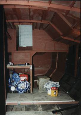
The engine has been fitted as it is sometimes easier to put in place before the deck is finalised. But it must be ensured that it can be removed at a later stage. This yacht has a raised floor in the aft section to increase the level floor area and to allow people in the galley to look out.
This is a Fay 32 which to 2005 has sailed over 30,000 miles and her owners have sent us a report from New Zealand saying how pleased they are and how she is gaining the reputation of being a fast ocean cruiser.
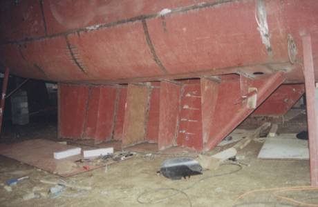
One of the keels on my Fay 40. It can be seen how the web floors are welded to the hull. They actually pass through the hull by an inch and fit into the interior floors. The bottom of the keel is 3/4" (18mm) and the forward edge is formed from thick wall tube.
These are all welded solidly together before the plates are fitted. The inner plate is in place and much of the interior finish welding completed, including solidly welding the central floor all round as this will form the front of a fuel tank. On the outer plate a joint is made at this web floor with a good weld gap. Then all three pieces are joined with a solid weld to finish the fluid integrity. The forward part of the keel will have 2 tons of lead ballast melted into it.
The bottom of the hull is 5mm steel and all the access holes into the keel, will have covers fitted by drilling and tapping so that they can be bolted down. A drilling tap that can be used in a reasonably slow drill makes short work of this operation.
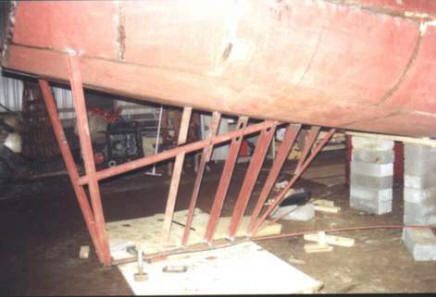
The skeg being formed. The shape has been marked on the hull and the bottom cut to shape and placed in position. It is over long at the rear and a temporary 'V' of angle tack welded to the hull holds it in position. Two temporary bars from the front of the bottom plate to the rear of each keel hold the front. The tube leading edge and rear flat bar are both in position. Web floors are fitted between the top shape and the bottom and the propeller tube is in the process of being fitted. The propeller tube will have a GRP tube epoxy glued inside later to ensure no corrosion.
A template of the side will be cut from thin plywood. Both sides will be cut. One will be fitted and the interior welds to the web floors made and the other side will have 'weld through' slots cut. This is shown on the next page.
This skeg actually has a volume of 30 gallons (140 litres) so is used as an extra fuel tank for those really long ocean passages.
©Paul Fay 2004