Links
Fay Marine Photographs 5
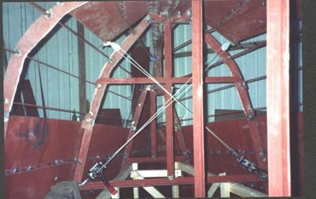
Internal view of the bow section. The wire winches are being used to pull the lower plates into position. When a lot of stress is applied to the framework like this, it is best to equalise it by pulling both sides at the same time.
These small winches will apply around one ton of pressure but if necessary this can be increased by using extra pulleys or using them at the end of a lever.
A close look at the stringers will show that they are held in place by a small 'spot' of weld to minimise the tendency to bend around the frame.

A nice picture of the inside on the way to completion. Note that the radius section is stitch welded to the frames. However it is unwise and most designers will advise not welding the topsides plates to the frames as this causes distortion, the 'hungry horse look' often seen on warships where everything is fully welded.
The topsides plates will only need welding to the stringers. This may cause a little longitudinal distortion, but this type of distortion is not so noticeable.
At the top of the photo can be seen typical drain/piping/services cut outs in the web floor. The web floors which will carry the cabin sole will have 2" x 1/4" (50mm x 6mm) flat bar welded across to provide a good base for the cabin sole to be bolted to.
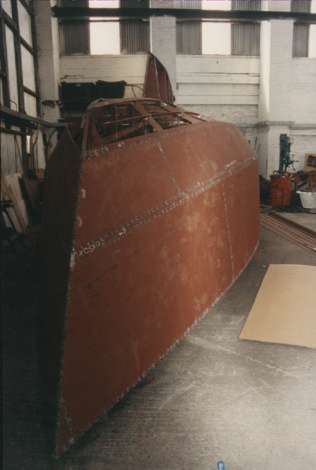
The plates are spot welded in place until the whole hull is plated.
None of the final welding should be started until the whole hull has been plated and all the plates spot welded at around 2" centres. The reason for this is to minimise distortion.
Excess distortion will be caused by over welding or an inappropriate weld sequence.
As in the picture the whole hull and keel should be plated and tacked in position. Once everything is in place the final welding begins. I prefer to make a light weld inside, then on the outside grind back to this weld with a cutting disk in the angle grinder to ensure penetration.
This is not the only method. Some people leave a weld gap between plates and only weld from the outside. Some allow the plates to touch and then weld with high amperage to penetrate, etc. etc. None seem to be incorrect. I have found the method which suits me and now as I am happy with it, I stick to it.
The truth of the matter is that yacht hulls of up to about 50ft are enormously strong when built of steel. Therefore even a relatively inexperienced welder, can with a little care and attention to detail produce a well built hull.
What is really important is to have a good weld sequence. Weld 2" and then move away a couple of feet and make another weld. Work around the hull doing this until all the joints are 2" of weld - then 2" gap - then 2" of weld. The next stage is to join all the welds. I like to take the angle grinder and touch the end of each weld to give a good lead in and out for the final weld, ensuring everything has good penetration. Many people say this is not necessary but it does not take long to do and ensures good weld integrity.
©Paul Fay 2004