Links
Fay Marine Photographs 11
Pages 10, 11 & 12 contain detail pictures of subjects that I am often asked about.
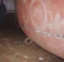
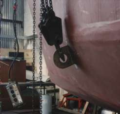
The lugs used to lift the upside down hull are cut from scrap bottom of keel steel. This will be a minimum of 1/2" (12mm) plate. There is a picture of a hull being turned over on the Fay 40 Radius Chine page
These lugs are welded on next to a frame which is solidly welded to the hull plating at this point. I also weld a piece of angle from the frame where the lug is welded to the centre of the headstock as an additional support.
Three lugs are needed. Two on one side at roughly 1/3 and 2/3 along the length of the hull. On the opposite side one lug amidships is needed.
Most cranes have a main lifting wire and a smaller auxiliary lifting wire. With spreader chains from the main wire to the side with two lugs and the auxiliary wire to the single lug the hull is lifted. Once in the air the auxiliary wire is lowered, then disconnected and taken the other way around the hull and used to level the hull, before lowering and standing the hull upright.
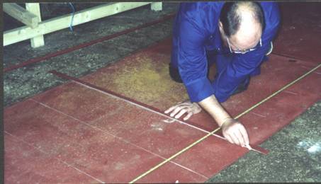
Marking out the topsides plates on a Fay 40 Radius Chine. The 8 sheets required are accurately laid out and one edge used as a straight line, being checked with a string line. Then lines are marked across at 12" centres. At each line, two measurements are given from the reference edge, one for the top and one for the bottom of the plate.
Once marked all the crosses are joined, along the length, with a straight edge. Any discrepancies due to inaccurate measuring will immediately become apparent and can be corrected.
The first time we tried this, to test the system, we laid out the plates and then gave Mo (my wife) a sheet of measurements to mark out.
After a few hours all the plates were marked and to Mo's horror without checking the measurements we cut the plates. They all fitted fine, giving total confidence in the system.
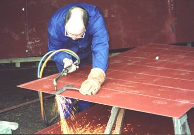
Cutting one of the plates. Once the plates for one side have been cut and the cut edge dressed by grinding, the plate can be laid on top of another sheet of steel and marked around to make the plates for the opposite side of the yacht. On a conventionally built steel yacht, where the plates are offered up and marked or templated, if the frames are accurate one plate can also be used as the template for the opposite side.
In this photograph an A.S.M.N. cutting nozzle is being used with a cutting guide made from flat bar with a round bar handle. The nozzle sits on the steel and against the cutting guide. With just a little training most people become proficient really quickly.
The chalk lines can clearly be seen in the photograph and chalk lines are also clearly visible when using the cutting equipment, which helps with accuracy.
©Paul Fay 2004