Links
| Please donate if you find this site useful. |
| Fay Marine |
| Yacht Plans |
| Anchors & Anchoring |
| Batteries |
| Battery Desulphation |
| Diesel Fuel |
| Electricity |
| Engines |
| Free Fire Design |
|
|
|
|
SOLID FUEL HEATER
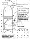
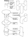
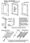
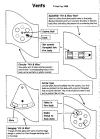
CLICK ON THE DRAWINGS AT THE END OF THE TEXT - THESE SHOULD BE PRINTED TO FULLY UNDERSTAND THE TEXT
In yachts and motorboats, caravans and motor-homes and in any other enclosed areas that can suffer from condensation, we need the driest form of heating possible. Gas, kerosene heaters and people can put a vast amount of water into the atmosphere, this will then condense on anything slightly cold. Windows, un-insulated linings and metal fittings start to drip turning the inside of a yacht or caravan into a mouldy, damp, clammy, nightmare.
I have found that solid fuel heaters dry the atmosphere beautifully. Even when itís cold, raining and thoroughly miserable outside a solid fuel heater will have the inside dry warm and comfortable in no time at all, they seem to positively suck the moisture from the atmosphere.
There are many kinds of solid fuel heater made for yachts, from the pot-bellied types to full kitchen 'ranges' that you can cook on. Home builders can construct most types, but the more complicated ones take an inordinate amount of time and so are not really economic to build.
Simple cabin heaters can be built from both round and square steel tubing. Personal aesthetic choice will determine whether to choose round or square, but for ease of construction and maintenance then square should be chosen. In addition, if you want to fix the heater to a bulkhead rather than have it free-standing (screwed to the sole or plinth) then square is easier and neater. For these reasons I will describe building a square version; building a round version is virtually the same, the design will just need slight modification.
The size of the heater depends on two things, first the size of your yacht and second the area where the yacht is kept. In southern England a 28 footer and a 32 foot yacht with a separate aft cabin have both used fires made from 4" (100mm) box tube to heat the main and forward cabins. In the same area two 32 foot yachts used 6" (150mm) box tube to heat the whole yacht. In Denmark, a yacht that is lived aboard all year round uses 10" box tube to heat the whole of this 38-foot yacht. This also provides hot water via a water jacket and hot water is also pumped to small radiators in the forward and aft cabins. The internal volume of a caravan or motor-home tends to be slightly more than a yacht of the same length, so a larger version should be chosen for these applications.
These sizes are about correct for normal weather conditions in these areas. If building a round fire the internal area should be kept the same. I.e. The internal area of the four inch fire is - 4" x 4" = 16 square inches. The six inch fire has an area of 6" x 6" = 36 square inches.
If you plan to go anywhere colder it will be sensible to go up a size, or perhaps fit two, one at each end of the yacht. It needs to be understood that an oversized heater may be slightly uneconomical when it is not being used to its capacity.
The depth that the fire can be filled to should be slightly greater than the size of the tube that is used. I.e. A four inch square fire will need to have about five inches above the grate for coal. Then three inches for the door and above this a minimum of one and a half inches as a smoke trap if the chimney exits from one side. This gives an above grate height of 9 1/2 inches.
Below the grate on all the fires around 3 to 4 inches should be allowed for the ash to collect. If the fire will stand on the cabin sole or a plinth then an extra two inches should be allowed below the bottom of the ash trap to stop any heat transfer to the sole or plinth.
This gives a total tube height for the four inch fire of around 14 1/2 inches. An allowance of half an inch must also be made for the thickness of the steel that forms the bottom of the ash trap and the grate, which brings the tube length to 15 inches.
If the chimney exits through the top of the fire, rather than to one side, then the volume of the smoke trap at the top of the fire can be reduced to almost nothing. This keeps the height of the fire to the minimum and on the large versions still allows room on the top for cooking.
TOOLS.
Anyone who maintains their home or yacht will probably have most of the necessary tools. These are: - Files, drill, angle grinder, small arc welder, (a 100amp welder is good enough for most small DIY jobs such as this), a few small taps to thread some of the holes in the fire body and finally access to an Oxy-acetylene cutting torch, preferably with an acetylene sheet metal nozzle (ASMN). Most of us donít have a gas cutter, but it is a simple operation to mark where the steel needs cutting then take it to your local steel fabricator who will only take a few minutes to cut it out. To give the cutting torch an easy start a 3mm hole should be drilled at each corner of the hole to be cut.
Alternatively the larger holes can be cut with a cutting disc in an angle grinder although this tends to make a slightly wider cut.
Large circular holes (such as for the chimney) can be cut by marking a circle, then drilling small holes all around the edge that are nearly touching. Finally these holes are enlarged until they all join, when the middle will fall out.
On the body of the fire and any of the parts that are 3mm or thicker, the parts can be held together by drilling and tapping the holes or simply by bolting together. 4mm zinc-plated setscrews work well and remain relatively easy to un-screw after the fire has been used.
DESIGN.
When constructing the fire there are a few things that need to be considered.
The first is to make sure that the top of the door is lower than the chimney. This is so that when the fire is being lit or re-filled the smoke goes up the chimney, not out the door and into the cabin.
The size of the chimney and vents are important. The following is a list of sizes that are approximately correct for various fires.
4" fire 6" fire 8" fire 10" fire
------- ------- ------- -------
Volume 64cu.ins 216cu.ins 512cu.ins 1000cu.ins
Chimney Dia. 1.5 to 2" 2.5 to 3" 3.5 to 4" 5.5 to 6"
Below grate vent 1.75sq.ins 1.75sq.ins 3sq.ins 4.5sq.ins
Above grate vent Not needed 2x1"x1/4" 3x1"x1/4" 3x1"x3/8" slots
Tube needed 15 ins 19 ins 23 ins 28.5 ins
The chimney can be fitted straight into the top of the fire, but if you like the idea of boiling a kettle on top, or of cooking on the fire, then it will need to exit at the back or on one side. In this case, the bottom of the chimney should be at an angle of around 45 degrees not horizontal, this is so that any soot that falls down goes back into the fire and doesn't cause a blockage.
For the chimney to 'draw' properly it should have a minimum length of around six feet. To avoid back draughts the top of the chimney should be well above the deck or roof. Two feet is the minimum and if the fire is being used while the yacht is next to a high quay or wall it will need extending further to avoid the down draughts often found next to vertical surfaces.
The top of the chimney should have a removable cap to prevent rain from entering and if the fire will be used where down draughts can be expected then an 'H' type top will be needed. This can be made removable by splitting and expanding a short length of the chimney tube to make it an interference fit that pushes over the chimney.
The chimney can easily be swept by pushing an extended 'bottle' or 'flue' brush down from the top.
Some way of 'riddling' (shaking) the grate must be provided to shake the ash down. In addition, the door to remove the ash should be as wide as possible so that a tray can catch all of the ash it when it falls and be easily removed.
CONSTRUCTION
An offcut of square tube should be purchased from your local steel supplier. This needs to have a wall thickness of 1/4" (6mm). Three pieces of the same thickness steel will also be required. These are for the top, the bottom and the grate.
Two short pieces of 3mm x 12mm flat bar or 3mm x12mm angle for the grate to sit on. A piece of 3mm x 25 or 30mm flat bar for the vent ash deflector and a small amount of 2mm plate and some tubing for the bottom of the chimney, is all that is required for the basic fire.
A length of preferably stainless tubing that will fit inside the tube welded to the fire and a piece of 2 or 3mm stainless plate for the deck and chimney top plates is needed to construct the chimney.
The square tube has the holes cut for the ash door, loading door, chimney and vent holes. The loading door must be large enough for the grate to pass through diagonally across the corners. The larger one's can be cut with a gas nozzle or angle grinder and the smaller ones with a drill.
Two pieces of flat bar are welded inside, or alternatively two pieces of angle can be bolted in for the grate to sit on.
Where the above grate vent holes are drilled a piece of flat bar needs to be fitted at an angle to stop the vent becoming blocked with ash and to stop sparks from coming out of the vent holes. This can either be bolted or welded in place. Only have vent holes and this deflector on one side of the fire, as otherwise it becomes impossible to fit the grate. After this the top and bottom are welded in place. The chimney is welded on and any locating lugs welded in place. The part of the tube below the ash trap can be cut away to form legs for the fire to stand on.
The grate is made from a piece of 6mm plate that is 3mm smaller than the inside of the fire from side to side, but 12mm smaller from front to back. This is so that the grate can be 'riddled' with a forward and backward motion. Holes are drilled in the plate and turned into slots by cutting between them with the gas cutter. The slots will need to be between 1/4" and 3/8" (6 to 9mm) wide. An alternative is to construct the grate by welding round bar between two pieces of flat bar. (see drawing)
On the underside at the front, a 12mm (1/2") nut is welded on. When the grate is in place, sat on the flat bars, the front of the box is marked and a hole drilled so that a 12mm bolt can pass through the hole and be screwed into the nut. This is used to riddle the grate by pushing it forwards and backwards. Shaping the head of the bolt and drilling a hole in it to take a tool is a finishing touch.
The two doors are very simply made by sandwiching the piece of steel that was cut out of the box, between two pieces of 2mm plate. The outer piece is 9 to 12mm larger all round and the inner piece a little larger at the bottom to form an inner locating lip. They are held together with small nuts and bolts.
Either a knob is made or a brass one is bought from the local DIY shop and a 'turn button' at the top holds the door closed.
In the accompanying drawing, a similar door is shown with a piece of fire glass set in the middle of the upper door so that the flames can be seen. The glass will need to be slightly smaller than the cut-out for it, to allow for expansion and sealed with fireproof rope, available from coal merchants or fire shops. The pieces of the doors are held together with 4mm bolts.
The upper door can be made extra deep and bars welded on the inside of the fire body, across the opening, so that more of the fire can be seen. When fitting these bars, drill a hole on each side of the fire that is a close fit for the bar, pass the bar through and spot weld to one side only. This allows for expansion of the bars without bending and for them to be replaced when necessary. Enough space must be left above these bars, at the top of the door for filling with coal and to allow the grate to pass through at an angle and be placed on it's supporting bars.
The doors that are shown in the drawings are located at the bottom and are designed to be lifted off to fill or remove ash. They could also be hinged from one side and a simple latch or turn button used to hold them shut.
Below the grate, either a circular 'hit and miss' vent or a screw type vent is fitted. Drilling three holes in a circle, then drilling three matching holes in a round piece of 2mm plate makes the hit and miss vent. With a bolt in the middle the plate can be rotated so that the holes are either lined up and open, misaligned and closed, or partially open.
The screw type is made by drilling a series of holes in a circle and in the middle a 6 or 8mm hole is drilled and threaded. A circular plate has a bolt welded through its centre and a knob fitted to the outside. This plate is screwed into the threaded hole and must be a good fit when screwed home to seal the vent holes. These vents may either be on the ash door or on the body of the fire to one side of the ash trap.
It has been found that these fires stay alight longer with no attention, if a small 'hit and miss' vent is positioned just above the grate. This is because when the fire is left for some time, the grate can become clogged with ash or the area below the grate can become full with ash, starving the coal of oxygen from the lower vent.
The chimney can be straight or cranked to suit your installation, but make sure that it is easy to sweep it, by only having gentle bends or by making the whole chimney easily removable. It fits inside the tube welded onto the fire so that any tar or soot falling back down the chimney remains within the fire. Care must be taken to make sure that this is a good seal to stop fumes from leaking. A double lip with one inside the part welded to the fire and one outside is preferred (see drawing). However the joint must be capable of absorbing the expansion and contraction of the chimney as it heats and cools.
Where the chimney goes through the deck or roof, this will need cutting back for several inches. A circle of stainless steel, 25mm larger than the hole in the deck, is welded to the chimney in a position where it can be screwed onto the deck.
The chimney should ideally end several feet above the deck and either an 'H' type top or just a simple rain cover completes the construction.
These fires are usually lit with a small piece of firelighter and some kindling. They will run on almost anything you care to burn including wood, peat and coal, but are most efficient when using one of the free burning types of coal.
In England one of the most efficient coals for this type of fire has proved to be Phurnacite which is egg shaped compressed coal or on the smallest fire Anthracite beans have been used.
If the fire will predominantly burn wood it will probably be worth constructing a slightly larger version, to increase the burning time between fills.
All surfaces around the fire must be protected with a heat-resisting barrier such as asbestolux; this is used to fire proof doors and is available from builder's merchants. This can be covered with thin stainless sheet as a decorative easy to clean surface.
Adequate ventilation must always be provided and the fire must not be left unattended. These fires and the chimney become very hot and protection for crew and children must be provided. Clothes, washing, and any other flammable material must be kept away.
To finish the fire there are many ways to enhance its appearance. On the top a stainless plate with fiddles around can be bolted on. This makes an excellent cooking surface. The fire can be painted with heat resisting paint or it can be stove enamelled. All the handles and tools can be made from stainless or brass and an attractive 'coal bucket' will complete the installation.
The drawings are clearer if downloaded to your computer and opened in Windows picture and fax viewer.
©Paul Fay 1998
These plans are for the private individual or club to construct a fire. Permission must be obtained from Paul Fay to use these instructions to build commercially.


